
The information on this page is paraphrased/summarized from Spencer Axani’s Detector Instruction Manual, in which you can find many more details and useful information.
Detector Anatomy
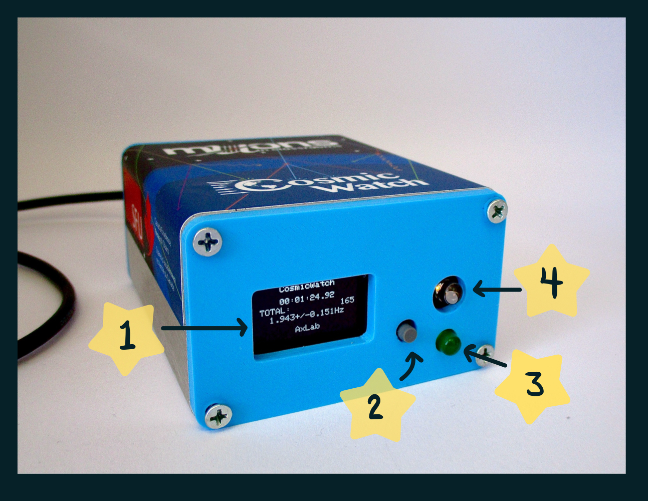
- Screen: Live updating information about recorded hits to detector.
- Reset button: clears detector memory to begin recording data again.
- Coincident LED: lights up when more than one detector is in “coincidence mode” and both detectors record a hit.
- Trigger LED: lights up when a hit is detected.
Display Screen
The screen shows a snapshot of the current data-taking period.
Cosmic Watch
Total runtime in HH:MM:SS.SS
TOTAL: total number of hits recorded in this run
hit frequency ± uncertainty in hit frequency
AxLab
Power and Coincidence Cables
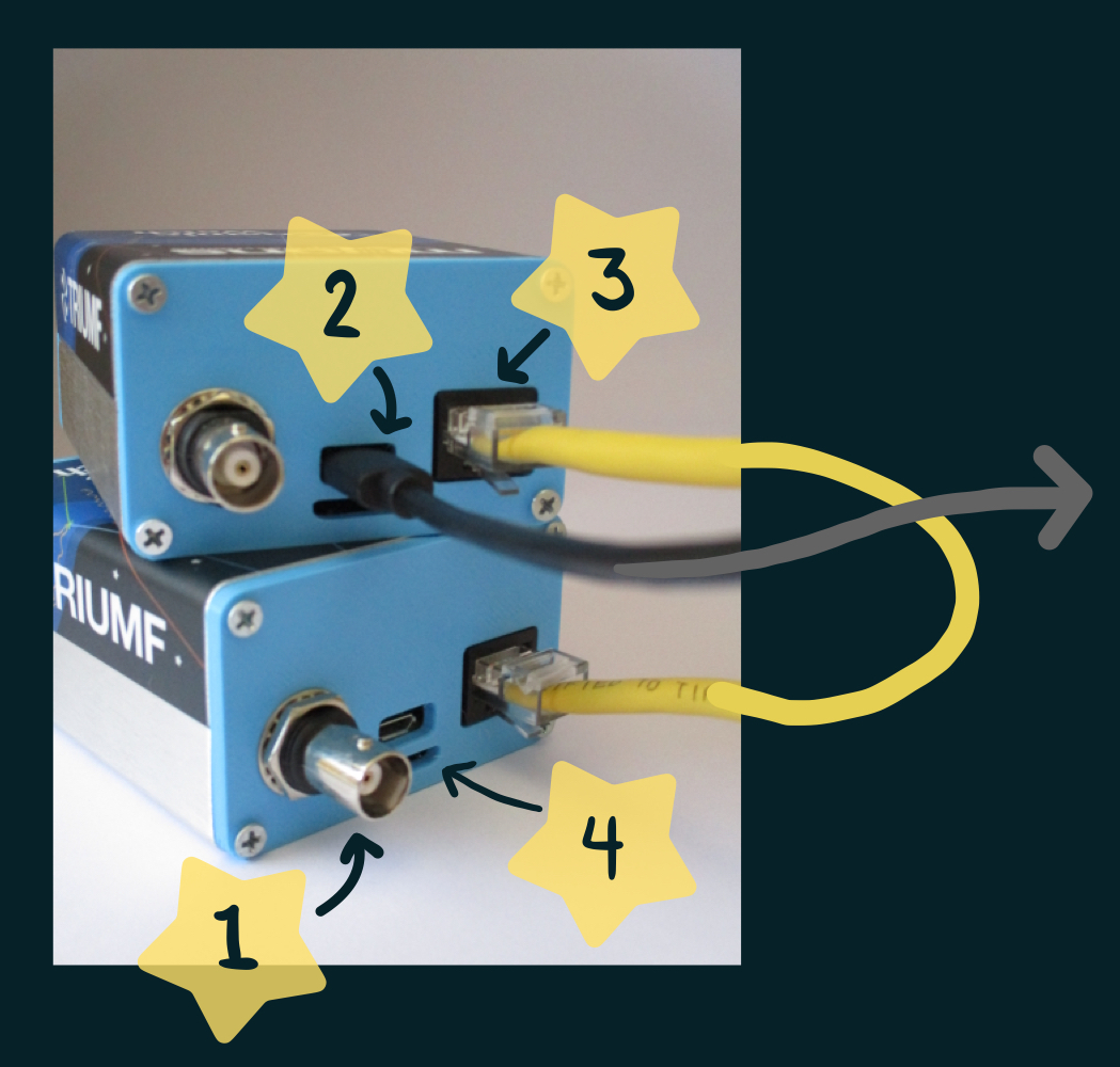
- SiPM Output: Can be used to view incoming waveforms on an oscilloscope.
- USB C Power Input: Connect to an outlet on a computer to power the detector.
- Ethernet Port for Coincidence: Connect two detectors together via their ethernet ports to run them in coincidence mode.
- SD Card Slot: Holds one microSD card.
A detector can be powered from any USB Mini to USB connector. It requires relatively low power, so a connection with your computer will work just as well as a connection with an outlet. Once the detector is plugged in, it will automatically turn on. If the detector is unplugged and then re-plugged in, this works like the reset button and a new data-taking period will begin.
To connect two detectors in coincidence mode, only one detector must be connected to a power source. The detector two is connected via an ethernet cable to detector one, and does not require any other connections.
Internal components
The detector is a USB-powered electronic device, and like any electronic, if you take it apart and tamper with it while current is actively flowing through it, you put yourself at a high risk of electrical shock. We recommend that you don’t take it apart. If you must, before anything else make sure that it is not connected to power.
Scintillator and SiPM
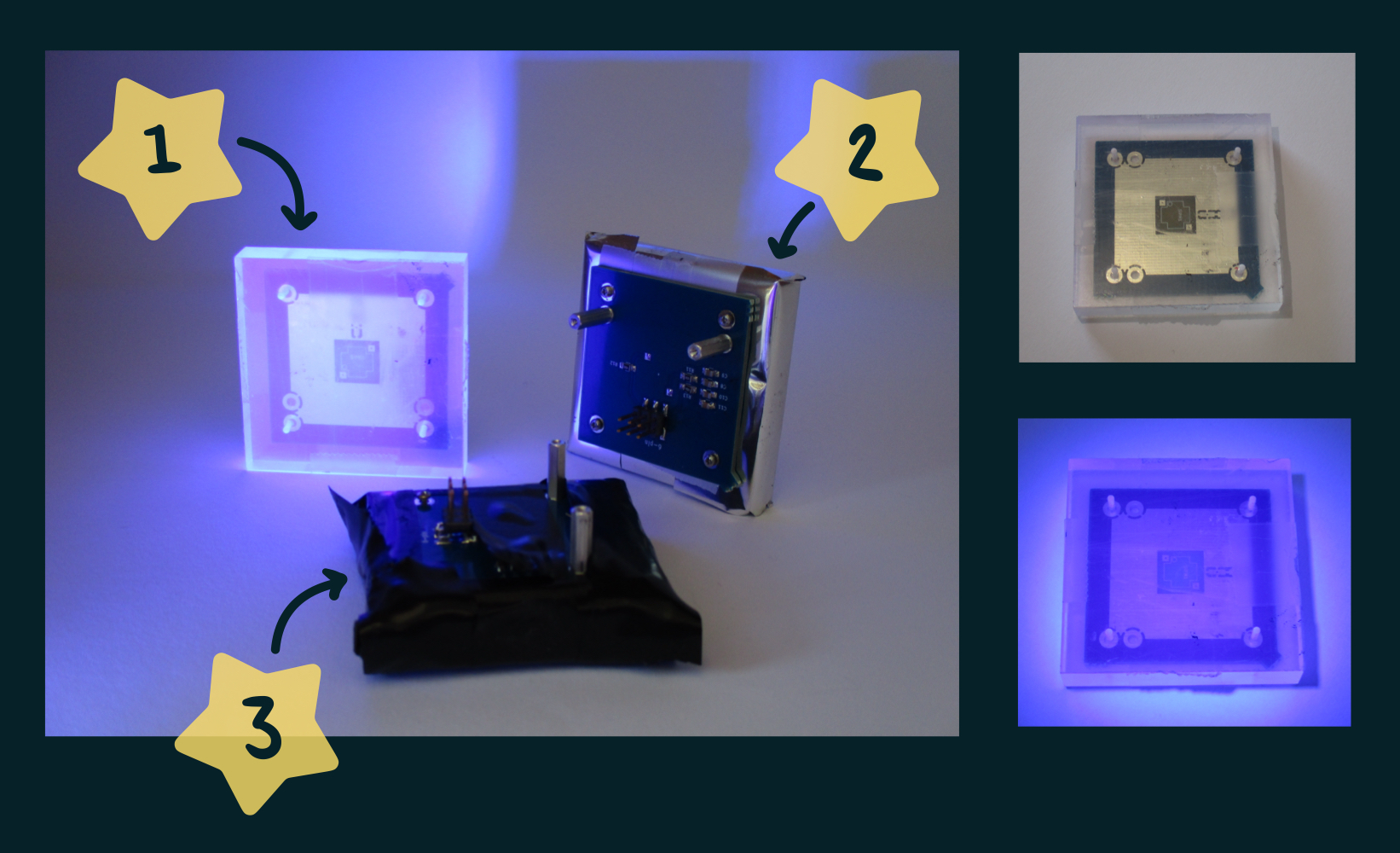
- Unwrapped Scintillator/SiPM: The scintillator is fixed to the board containing the SiPM and optical gel is used to smooth the connection between the chip and the plastic of the scintillator. When a scintillator is exposed to UV light, it glows (pictured).
- Partially Wrapped Scintillator/SiPM: The first layer of wrapping for the scintillator is reflective: this allows the photons produced by charged particles to be reflected back into the material as opposed to escaping the detection area.
- Fully Wrapped Scintillator/SiPM: The final layers of wrapping are done with black electrical tape. The goal of this now is to keep photons from the exterior environment out of the scintillator/SiPM environment, where they could affect signals produced by the system.
When charged particles traverse the scintillator, some of their energy is emitted as photons that are trapped and amplified within the scintillator. In general, for every 100 eV of energy which a transiting particle possesses, one photon will be released. The scintillator is attached to a silicon photomultiplier (SiPM) chip. When a photon hits the SiPM, there is a small current discharge into the detector circuit. More photons hitting the SiPM result in larger discharges.
Circuit Board and Raspberry Pi
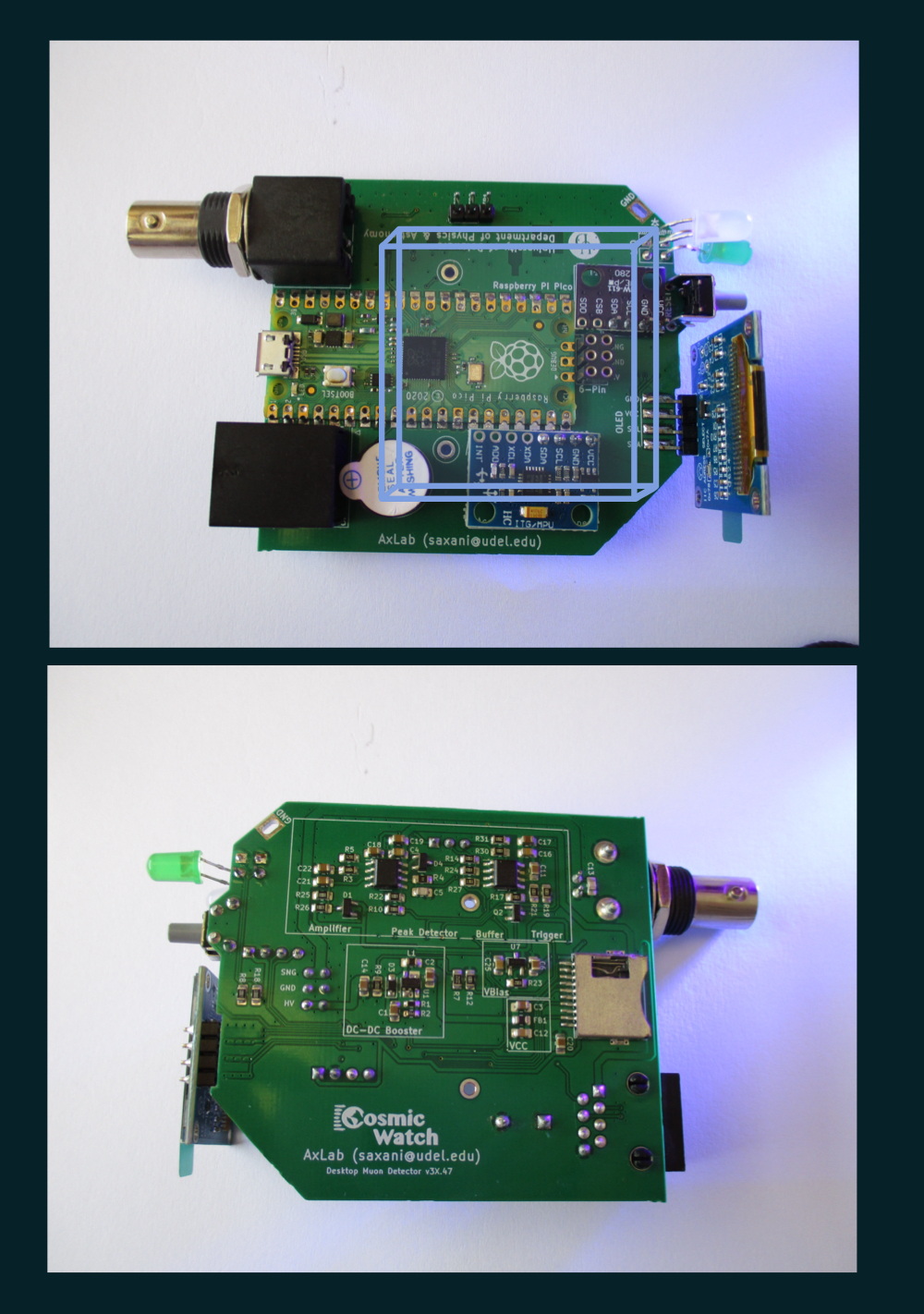
The current pulse from the SiPM is very small. The role of the circuit board is to amplify the signal and shape the signal into a useful form. Once the signal is cleaned and amplified, it can be read by the Raspberry Pi Pico (RPi) micro-controller. The RPi records information about the event on the SD memory card (if one is inserted), and talks to the rest of the circuit: the LED(s) will flash and the display screen will update.
Taking Data
A single detector can be used to detect atmospheric muons at a realistic frequency by applying an energy threshold that must be met by the recorded voltage pulse of a hit in order to qualify as a muon.
Alternatively, to filter out the natural radiation background which is picked up by the detector, two detectors can be connected together in “coincidence mode”.
Coincidence Mode
To set two detectors in coincidence mode, connect them with an ethernet cable, and then reset both detectors using the reset button within one second of each other. Only one detector needs to be powered.
Coincidence mode adds a column to the recorded data which flags each event as 0 (only one detector picked up a hit) or 1 (both detectors experienced the hit). Events flagged by both detectors are vastly more likely to be atmospheric muons: other particles do not travel in straight lines, do not deposit enough energy into both detectors, or are unable to pass through the detector casing.
Note that because atmospheric muons tend travel downwards to earth’s surface, stacking the two detectors on top of each other is necessary for collecting coincident measurements.
Recording Data
The recommended method for recording data is using a microSD card. With an SD card inserted, a new file is created each time the detector is reset (including being powered on/off). Data is stored in plaintext format with a .txt extension. A relatively small SD card can store months worth of data, which can then be easily transferred to your computer and uploaded to this website!
Available Variables
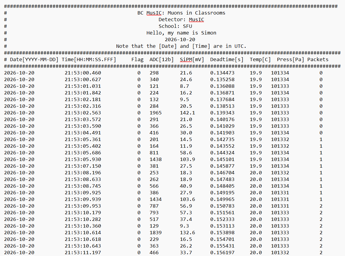
Each file begins with a short header naming the detector (the Detector: line), followed by one line per recorded hit:
- Date[YYYY-MM-DD]: The date of the hit, in UTC.
- Time[HH:MM:SS.FFF]: The time of the hit to the millisecond, in UTC.
- Flag: Identifies a coincident event, so only meaningful when a detector is in coincidence mode. 0 if an event is non-coincident, 1 if an event is coincident.
- ADC[12b]: Twelve-bit analog to digital converter (ADC) number for the signal pulse. An ADC measures an analog electrical signal and converts it into a digital number.
- SiPM[mV]: Calculated SiPM pulse height based on the ADC measurement, proportional to the amount of energy deposited into the scintillator.
- Deadtime[s]: Cumulative dead time since the detector was switched on: the total time it has spent busy processing hits, during which it could not record a new one.
- Temp[C]: Temperature measured by the internal sensor.
- Press[Pa]: Air pressure measured by the internal sensor.
- Packet: The detector groups hits into packets of ten and numbers them in order, starting from 0 in each new file; this column is the number of the packet each hit belongs to. Numbers may be missing, because the detector throws away packets whose rate is implausibly high — for example while it is being moved. A packet is a stretch the detector was certainly recording for, which is what makes it possible to measure a rate from the file yourself: for each packet, divide the number of hits after the first (nine, for a packet of ten) by the time from the first hit to the last, minus the dead time accumulated over that stretch. The Data page explains how the plots use this.
Safety
In general, the detectors are as safe as any other low-power USB-powered electronic device. They are powered entirely through a standard 5-volt USB connection, and the supply voltage is further regulated by the Raspberry Pi Pico and additional onboard voltage regulators before reaching the various electronics.
The only higher voltage present inside the detector is generated by an onboard DC-DC boost converter used to bias the SiPM. This converter is capable of supplying approximately 30 V at a maximum current of about 40 mA (in the case of a short), which presents a low safety risk for standard conditions like dry skin contact. In practice, the operating current is very small, and the available power is extremely limited.
From an electrical safety perspective, there is no exposed high-voltage circuitry, no hazardous stored energy, and no shock hazard during intended use. The detector has been designed as a low-power educational instrument, its electrical safety is considered to be comparable to that of other simply USB-powered electronics like microcontrollers.
In short: do not open the detector and tamper with its internals when it is powered on.
It is also helpful to note that the detector is only a detector and nothing more, passively noticing what is already present in the everyday environment that we all live in. It does not generate or store any high-energy particles and carries none of the safety risks associated with the types of particle physics apparatus that do handle that type of task.